|
<< Click to display Table of content >> Ground and DTM |
  
|
|
<< Click to display Table of content >> Ground and DTM |
  
|
The first (compulsory) stage in the creation of a MithraSIG Model involves modeling the relief in linear/punctual form and DTM form. In fact you need both of these definitions for the reasons set out below.
The ground (lines and points)
This 'Ground' overlay represents the modelling of the ground during acoustic simulations.
When calculating the propagation of rays, the software determines all intersections with lines/points marking out the terrain.
The Digital Terrain Model (DTM)
The DTM is used during construction of the model and 3D views. It tells you the height above ground of the model at any given point. It is made up mainly of the terrain but can be enhanced with the edges of building footprints as well as other objects (see Updating DTM chapter)
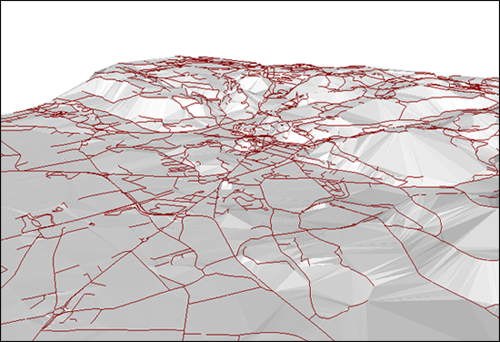
The Digital Terrain Model involves facetizing the surface of the terrain. One of the classic methods, used by MithraSIG, involves the application of a triangulation i.e. facetizing the ground in the form of triangles that join all the topographical data points of the relief. This produces a TIN (Triangulated Irregular Network) type DTM.
MithraSIG can generate a DTM from vector data (points, lines, polygons). MithraSIG applies Delaunay triangulation. Contours, 3D feature lines, edges of building footprints, walls, edges of road and rail platforms, etc. are treated as lines of force i.e. that they all produce the sides of triangles so that the straight line sections between two successive points are part of the surface modeling. For more information on triangulation, go to the chapter Default parameters of the model.
The Digital Terrain Model is also essential to MithraSIG for the input of buildings, walls and sources, in terms of altimetric positioning.
With the exception of 3D viewing and draping of orthophotos, there is no need to load the Digital Terrain Model in the GIS (file named 'Var_X_DTM.obj'). In addition the DTM is retranscribed into lighter grids for viewing only (file named 'Var_X_DTM.obj').

3D view of ground (TIN) and contours