|
<< Click to display Table of content >> Creation of the ground |
  
|
|
<< Click to display Table of content >> Creation of the ground |
|
Terrain integration is the automatic creation of Ground Point and/or Ground Line objects from a data source.
This data source can be:
•Vector data (points and/or lines): point set (x,y,z), contours, 3D feature lines (edge of road, top of bank, bottom of bank, lake edge, etc.).
•Raster data (grids).
It is possible to take into account different data sources by carrying out several Ground integrations by keeping the Reset option unchecked.
To create the ground:
•From the ribbon Model, click on the ![]() button in the group Integration.
button in the group Integration.
•Ground and DTM creation interface is displayed:
")
Intégration du terrain (Points et lignes)
In this window, you must first choose the creation mode (Points and break lines, Points and vertices, Grids), then configure the overlay containing the data used as a reference.
Points and break lines creation mode
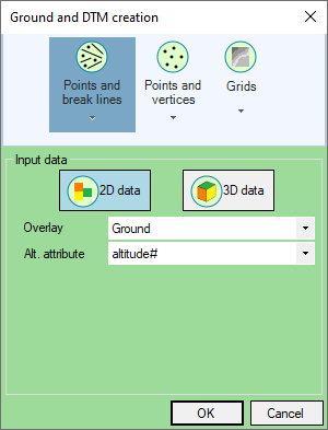
The Points and break lines creation mode allows you to generate Ground Points and Ground Lines from Point type and Line type data.
Objects of type Point on the original overlay will generate Ground Points.
Objects of type Line on the original overlay will generate Ground Lines.
Original overlay must therefor contain points and/or lines.
The 3D data mode allows to determine the altitude (z-coordinate) of created objects from the z-coordinates of the original objects.
The 2D data mode allows to determine the altitude (coordinate z) of created objects from an attribute present on the original objects. This mode will be preferred if the original data does not have a z coordinate (not filled in, or wrong).
Points and vertices creation mode
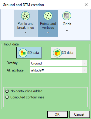
The Points and vertices creation mode allows you to generate Ground Points from Point type and Line type data.
Objects of type Point on the original overlay will generate Ground Points.
will be exploded so that each vertex generates a Ground Point.
Objects of type Line on the original overlay will be exploded so that each vertex generates a Ground Point.
Original overlay must therefor contain points and/or lines.
The 3D data mode allows to determine the altitude (z-coordinate) of created objects from the z-coordinates of the original objects.
The 2D data mode allows to determine the altitude (coordinate z) of created objects from an attribute present on the original objects. This mode will be preferred if the original data does not have a z coordinate (not filled in, or wrong).
Contour lines can then be generated from the points obtained by checking the Computed contour lines option.
Mode de création Grilles
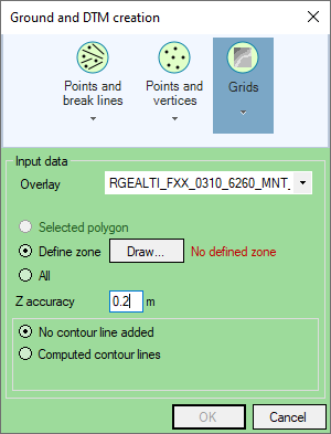
The Grid creation mode allows you to generate Ground Points from one or more grids (for example, an RGE Alti 5 m grid from the IGN).
Each grid has pixels (larger or smaller square depending on the resolution of the grid).
A Ground Point will be generated at the center of each grid pixel. Its altitude will be determined from the value associated with the pixel.
To take into account only a certain area and not the entire grid or grids, you can define a polygon that will serve as a punch.
This polygon can either be drawn (by choosing the Define zone option and clicking on the Draw... button), or correspond to the currently selected polygon.
The points obtained can be very numerous, then causing slowness in the generation of the DTM as well as in the simulations. To reduce this number of points, it is possible to use the Z accuracy parameter. This parameter allows you to indicate a tolerance in Z used to remove certain Ground Points considered as not essential (because they have little or no impact on the final DTM obtained ). For more information, see Z Accuracy.
Contour lines can then be generated from the points obtained by checking the Computed contour lines option.
Ground overlay and associated files
A "Ground" overlay is created. It corresponds to the file named "Var_X_Terrain.bds" created and saved in the variant directory.
At the same time, the DTM is generated and a "DTM" overlay is added to the composition. It corresponds to the files named "Var_X_DTMGrid.bds" and "Var_X_DTM.obj" created and saved in the variant directory. These two files correspond to the results of the triangulation respectively in grids and in TINs (triangles).
The "Var_X_DTMGrid.bds" file contains grids and is inserted into the composition. The resolution of these grids is defined in the model's default parameters and is automatically recalculated if the total number of grids exceeds the number of 120 (each base grid gathering 1000 x 1000 pixels). This file is not essential and is just a visualization of the calculated DTM.
The "Var_X_DTM.obj" file contains a TIN. It is not inserted (often bulky) but is essential and is used when draping objects.
The model's default parameters allow you to modify certain triangulation parameters in order to handle large amounts of data or to filter certain flat triangles. The number of points (with line vertices) is limited to 20,000,000.