|
<< Click to display Table of content >> Add a noise barrier |
  
|
|
<< Click to display Table of content >> Add a noise barrier |
  
|
•From the ribbon Model, click on the button ![]() in the group Add items.
in the group Add items.

•The Line tool is active. Design the geometry corresponding to the new object. Finish the entry by pressing the key Enter.
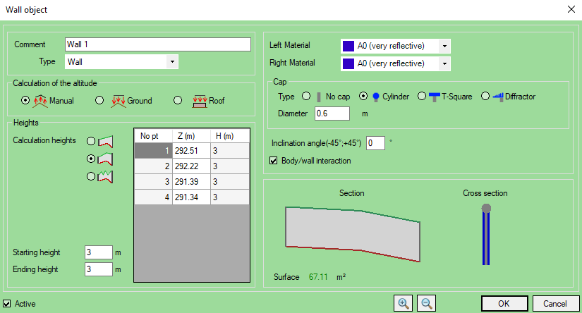
•The Barrier object box is displayed so that the parameters for the input line can be entered:

Barrier interface
oEnter a name for the wall in the Comment field to distinguish the wall from another in the interfaces referring to that wall. By default, the wall takes an unused name.
oSelect a Type of barrier.
There are two options: Barrier and Retaining barrier.
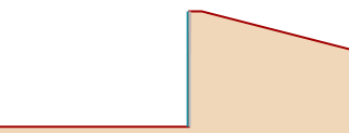
In the case of a Retaining barrier, a single type of material must be entered and its side (left/right) chosen in the digitalization sense. When creating a retaining barrier, the ground is rising behind the barrier.
That means the ground starts at the z max from the barrier. That is not the case with a "classic" barrier.
 Cross section of a "classic" barrier |
 Cross section of a retaining barrier |
oSelect a Calculation of the altitude mode:
▪Manual: The z of each vertex is defined explicitly by the user.
▪Ground: The altitude is determined dynamically based on the ground below the wall. The wall can be considered as a 2D object adapting to all ground updates.
A modification of the ground (addition of a road, creation of a mound, ...) automatically leads to a modification of the altitude of the wall.
This mode should be preferred if you draw a wall or if you do not know the exact 3D information of the wall.
▪Roof: In the case of a wall on a building, the altitude is determined dynamically basing on the roof of that building.
If there is no building below the wall, the altitude is determined basing on the ground below.
oSelect a Calculation heights method (See Mound).
oEnter a Starting and an Ending Height (the diagram is automatically modified).
oLeft and Right materials (left or right for retaining barriers). The default materials are:

Any additional materials chosen by the user will be added to this list. The parameters of these materials can be seen in the materials interface.
oCheck the Body/barrier interaction option if you want the wall to interact with any railway sources.
The body/barrier interaction adds a series of reflections (3 in MithraSIG) related to Train / Barrier interactions.
Indeed, in the presence of a screen, rays from the source are reflected successively between the screen and the side of the train.
Under these conditions, the rays move between the obstacle and the body of the railway vehicle before they diffract on the summit ridge of the obstacle (see French standard NMPB 2008).
Concretely, the interaction takes only effect when there is a screen between the receiver and the railway source. Higher values may result from the body/barrier interaction effect.
For the receivers between the screen and the source, reflections on the screen are taken into account as usual in the ray simulation. In this case, the body of the train is not taken into account.
Good practice: for the railways in urban areas, it is advisable to make absorbent screens source side (Alpha 0.8). In this case, the body/barrier interaction influence decreases a lot to become almost zero.
oThe tilt (Inclination) parameter is used in simulation as an extension of methods. Simulation are valid with tilt between -45° and 45°. Convention: angle> 0 for a tilt on the right relative to the direction of the line.
Warning: simulation with tilt noise barriers are in Fresnel reflection mode. If a simulation has tilt wall with specular reflection, the reflection mode of the simulation is transformed in Fresnel reflection.
oThe cap diffractor corresponds to the 4Silence barrier Whiswall©, with a diffracting top. This wall was characterized experimentally and numerically in terms of noise attenuation performance. A calculation procedure suitable for existing engineering methods was developed at TNO and later improved by 4Silence and CSTB to satisfy a wider range of barrier configurations.
•Click OK to confirm.
|
Noise barriers are visible in 2D and 3D with the corresponding material color. |
|---|