|
<< Click to display Table of content >> Integrating mounds and banks |
  
|
|
<< Click to display Table of content >> Integrating mounds and banks |
  
|
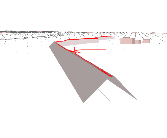
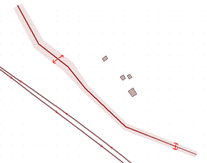
Input data: a 3D line representing the top of the mound. The height of the mound corresponds to the difference in elevation between the 3D line and the ground. The width of the mound is calculated according to the height and slope of the mound.
 3D line representing the top of the mound required during input |
 The mound has a variable width depending oo the 3D line used when integrating, and the elevation of the ground on which it is situated (the slope being considered as fixed) |
Pour intégrer les buttes et talus :
•From the ribbon Model, click on the button ![]() in the group Integration.
in the group Integration.
•Click on the button Mound bank.

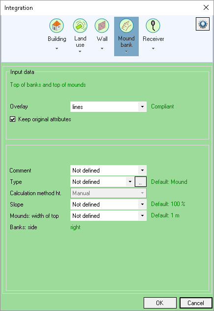
Integrating mounds / banks
•Enter the name of the Overlay containing the data to be integrated. This data must be 3D lines:for consistency, the overlay must contain lines only.
•Enter any attributes to be used to configure the objects:
oA Comment.
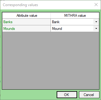
oThe Type (mound or bank). Use the ![]() button to access the interface corresponding to the selected type. Then make the values of the attributes correspond with the original MITHRA values.
button to access the interface corresponding to the selected type. Then make the values of the attributes correspond with the original MITHRA values.

Corresponding values of type
oThe Slope.
oThe width at the top of the mounds.
The values in green are the default values used, in particular when no attribute is specified. These values can be configured in the default terrain values interface.
The Keep original attributes option allows you to keep the attributes of the objects on the original overlay.
The Rounded coordinates option allows you to round coordinates of all line vertices.
The Add vertices on DTM intersections option allows you to create vertices on DTM triangles intersections (compliance with existing DTM).
The Reset option deletes all old mounds and banks that are already present. When this option is unchecked it is then possible to add objects to an existing 'Ground' overlay.
•Click OK to confirm.
The mounds/banks are added to the project in the 'Ground' overlay. This corresponds to the 'Var_X_Terrain.bds' file created and saved in the project directory.
|
At the end of the integration, a message appears if there are mounds/banks that could not be created: they are then at an elevation of -999.0 m and must be corrected by the user. If there have been problems (missing or inconsistent attributes), an XML error file opens automatically and show a list of errors classified by type. The incorrect origin line is identified either by its object identifier or by the coordinates of its first point (if the origin data set has been inserted and is not modifiable).. |