|
<< Click to display Table of content >> Representation of the antennas |
  
|
|
<< Click to display Table of content >> Representation of the antennas |
  
|
The term transmitter regroups antenna and emission system.
2D representation
There are 4 symbols available for an antenna depending of its orientation of emission (omnidirectional, directive, directive with a left/right electric azimuth)
For each symbol, there are 2 ways to display an antenna (see chapter style).
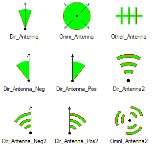
Symbole des antennes
The name of the antennas is visible in the graphic view with a dedicated theme. If 2 antennas are superimposed and have the same orientation (tolerance of 5° on the azimuth), the name of the second antenna is automatically moved in order to display properly the names.
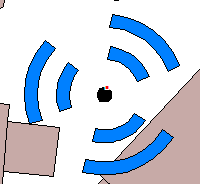
Omnidirectional antenna
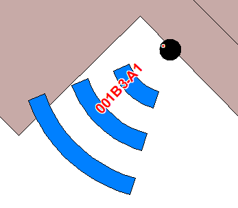
Directional antenna
Antenna with an emission not aligned with the azimuth
With the new MIMO antennas, some antennas have their main emission not aligned with the physical azimuth of the antenna. MithraREM reads the Patterns files (MSI) and computes the angle of the main emission depending of the horizontal diagram.
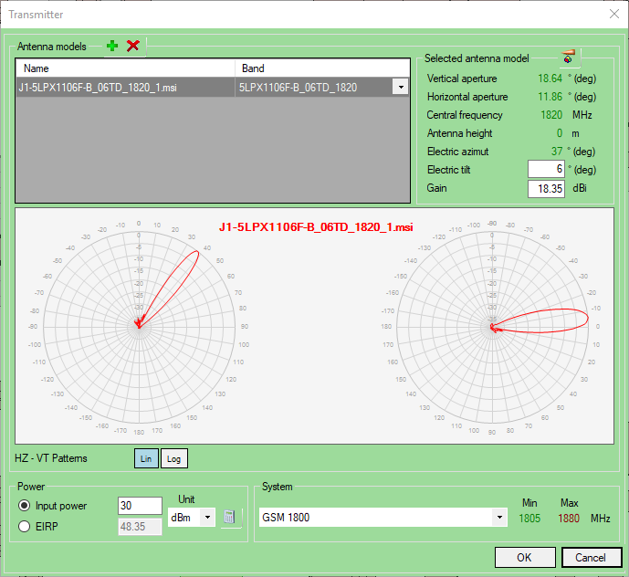
To take into account this electronic azimuth in the graphic view (for a better view of the project), if the electric azimuth is less than -5° or more than 5° compared to the physic azimuth, MithraREM uses a special symbol to inform the user that the antenna is an antenna with an emission not aligned with the azimuth.
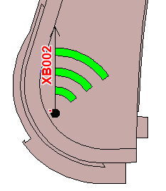
Representation of an antenna with an emission not aligned with the azimuth
The electric azimuth and the associated symbol are calculated from the antenna pattern. The symbol is only used for a better view of the project and is not taken into account in the simulation.
3D representation
Only visible in the 3D view: 3 faces composed the antenna. The red face gives the direction of the emission.
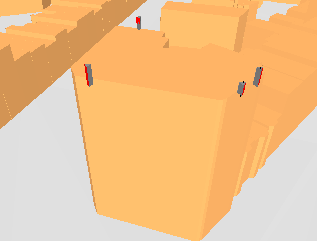
3D representation of the antennas