|
<< Click to display Table of content >> Radiation pattern |
  
|
|
<< Click to display Table of content >> Radiation pattern |
|
This function draws a horizontal and/or a vertical grid (only visible in the 3D view) corresponding the the theorical emission of an antenna relative to an emission system (the ground and the buildings are not taken into account in this case). The direction of the grid is the one of the azimuth of the chosen antenna.
The function is available after the selection of one or several antennas by clicking on the button  , in the tab Simu - Renderings, groupe Renderings.
As the diagrams can be created from several antennas, the grid computed shows the accumulation of the selected antennas.
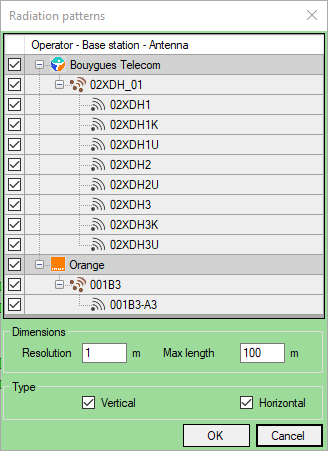
The selected antennas are listed to activate/deactivate them in the diagram.
•Max length: total length of the diagram taking into account the the diagram begins at 25 meters behind the antenna.
•Resolution: value used for the grid rendering. Finer is the resolution, larger will be the grid (file size).
•Type: Vertical or Horizontal or both.
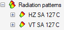
The diagram are created in specific overlays, one for horizontal and one for vertical.
Modify the color
The color of the diagrams can be modified in the default options, tab Antennas. This has to be done before the creation of the diagrams.

Radiation diagram in 3D view