|
<< Click to display Table of content >> Add an antenna |
  
|
|
<< Click to display Table of content >> Add an antenna |
  
|
To add an antenna, from the ribbon Model, click on the button ![]() in the group Ajout d'objets.
in the group Ajout d'objets.

Add an antenna
Then, click where you want to place the antenna. The setting interface is displayed to enter description and position.
Description
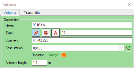
The description of an antenna is composed of information that has to be set in the first frame of the interface.

Description of an antenna
•Name: This mandatory and unique field allows to view the antenna more precisely during the manipulation in the software (list of antennas, simulations, renderings, etc).
•Antenna type: determines the symbol of the antenna in the graphic view. It is used to show the type of the directivity of the antennas (ominodirectional, directive, etc.) A comment is optional and can be added freely.
•Comment: free entry allowing to add a custom information.
•Base station: optional information but recommended for the management of the antennas. The antenna can be linked to a base station. The drop-down list shows the base stations defined in the software. In the case of mobile telephony networks, the base stations can correspond to the BTS of the operators. This information will be useful during the simulation results. New base stations can be added from this windows.
•Antenna height: Physical height of the antenna.
Position
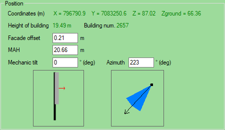
The information in this frame is used for the simulations.

Position of an antenna
•Coordinates: coordinates X/Y, Z on the ground (Zground). Altitude from the ground (Z) of the antenna corresponds to Zground+MAH. Information automatically computed by the software.
•Height of building: height of the building if the antenna is located on a building.
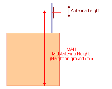
•MAH (Middle Antenna Height): height of the antenna from the ground.

Cross section showing the location of an antenna
•Azimuth: orientation in degree, 0° corresponds to the geographic North.
•Mechanic tilt: physical orientation of the antenna in degree, negative for downward tilt and positive for upward tilt
In the interface, the 2 illustrations Azimuth and Tilt help to visualise the parameters defining the orientation:
•The Tilt illustration shows the antenna in relation to a fictive support. The arrow gives the main orientation.
•The Azimuth illustration displays the azimuth of the main direction.