|
<< Click to display Table of content >> Create the ground |
  
|
|
<< Click to display Table of content >> Create the ground |
  
|
The topographic relief data that can be integrated into MithraREM is as follows:
•Vector data: point set (x,y,z), contours, 3D feature lines (edge of road, top of bank, bottom of bank, lake edge, etc.).
•Raster data (grids).
It is possible to integrate different sources of relief data by deactivating the Reset option (which appears if the ground has already been created) and thence by carrying out several Ground and DTM creations in succession.
To create the ground:
•From the ribbon Model, click on the button ![]() in the group Integration.
in the group Integration.
•Ground and DTM creation interface is displayed:

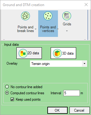
Input of ground (Points-Vertices)
Vector data
This data relates to the Points and break Lines and Points and vertices buttons.
In the event that the input data contains a single point set, MithraREM may be able to produce contours that can be added to the ground.
The data can be in 3D (i.e. x,y,z) or in 2.5D (i.e. with the attribute z). The MithraREM interface thus allows the operator to specify the data used and to choose from amongst the attributes the one that contains the elevation, for example.
•Select the type of source data:
oPoints and break lines if you have points and/or lines (these lines will be input at the same time as the lines of force in the DTM that will be created).
oPoints and vertices if you have points and lines (the lines will be broken down into points called vertices).
•Select the type of database:
o2D data if your data is 2D.
o3D data if your data is 3D.
•Select the Overlay containing the source data.
•If your source data is made up of lines or points and lines in a 2D dataset, enter the attribute containing the Elevation.
•If your source data is made up of points and lines, select one of the following options:
oNo contour line added no contours are created.
oComputed contour lines to create contours that will be input into the ground, in this case enter the Interval between contours and if you want to keep points used (to calculate contours).
•Click OK to confirm.
Raster data
This data relates to the Grids button.

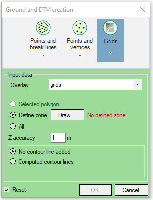
Input of ground (Grids)
•Select the Overlay containing the source data (grids). This overlay must contain object grids.
•The area must be defined by a polygon:
oEither pre-selected: the area must be defined by a polygon pre-selected before the use of the function.
oOr to be designed (Define zone) via the ![]() button.
button.
oOr that will take the full extent of the data.
•Z accuracy : clean tolerance of points to keep important points (see Z Accuracy).
•Computed contour lines: automatic creation of contour lines. It is necessary to defined an interpolation pitch in z for contour lines created from the points of the grid.
Example: for a pitch of 2 meters, MithraREM will create contour lines every 2 meters in z.
•Keep used points: when creating contour lines, keep the ground points extracted from the grid. This option makes the data bigger.
The ground is added to the project and a 'Ground' overlay is added to the composition, it corresponds to the 'Var_X_Terrain.bds' file created and saved in the project directory.
The DTM is added to the project and a 'DTM' overlay is added to the composition, it corresponds to the 'Var_X_DTMGrid.bds' and 'Var_X_DTM.obj' files created and saved in the project directory. These two files correspond to the results of the triangulation in grids and in TIN (triangles) respectively.
The 'Var_X_DTMGrid.bds' file contains the grids and is inserted into the composition. The resolution of these grids is defined in the model's default parameters and is automatically recalculated if the total number of grids is greater than 120 (each base grid containing 1,000 x 1,000 pixels). This file is not essential and is just a view of the computed DTM.
The 'Var_X_DTM.obj' file contains a TIN. It is not inserted (because it is often voluminous) but it is essential and is used when draping objects.
|
The model's default parameters allow you to modify certain triangulation parameters in order to handle large amounts of data or to filter certain flat triangles. The number of points (with line vertices) is limited to 20,000,000. |
|---|