|
<< Click to display Table of content >> Antenna model |
  
|
|
<< Click to display Table of content >> Antenna model |
  
|
An antenna model is defined by the antenna manufacturer. Antenna models are provided in a folder of the software (default path: C:\Program Files\Geomod\MithraREM\AntennaModels).
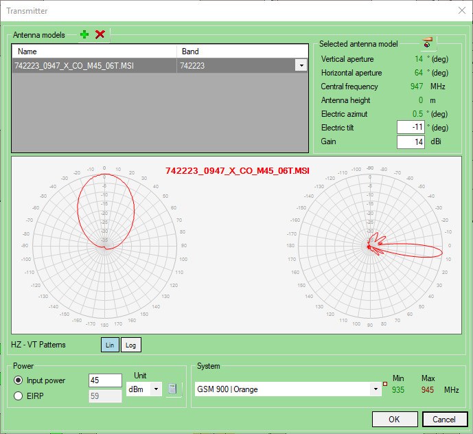
The models can be added from the interface Antenna models, by clicking on the button ![]() . The antenna models show the radiation diagram of an antenna for a specific frequency. MithraREM allows to set several antenna models to create antenna antenna variants.
. The antenna models show the radiation diagram of an antenna for a specific frequency. MithraREM allows to set several antenna models to create antenna antenna variants.
A model can have several frequency bands, in this case a second drop-down menu (Band) allows to choose the wanted diagram.

Ajout d'un système d'émission
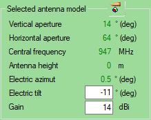
Once the model and eventually the band are set, information extracted from the model is displayed:

Antenna model settings
•The aperture of the model in the frequency band.
•The Central frequency of the transmitter.
•The Height (as a guide).
•The Electric azimuth.
•The default Electric tilt of the model.
•The default Gain of the antenna in dBi. The gain of the antenna model is always converted in dBi (some models have their gain in dBd) using the formula:
dB(isotropic) = dB(dipole) + 2.15
Antenna models like "MSI Planet" (generally use by antenna constructor) are far-field diffraction models, meaning that they are valid when we are far enough of the antenna to be considered as a point. Usually, considering they are valid only 7x faraway than the antenna height (to be consider as a point). The physic reality of the antennas (with a height nearby one meter) implies to not take into account any geometric obstacle (a low wall on the edge of roof) near the antenna for a correct use of this type of radiation diagram. It is possible to take obstacle into account near the antenna in MithraREM with a finer modeling of the radiation of the antenna (representation by a dipole for example).