|
<< Click to display Table of content >> Antenna variants |
  
|
|
<< Click to display Table of content >> Antenna variants |
|
MithraREM allows to calculate variants of antennas to perform several configuration of an antenna in one time.
Example of variants on electric tilts
When a RET - Remote Electric Tilt antenna is installed, the electric tilt can be modified remotely. You may want to know the theoretical maximum exposure for all the tilt values.
For an RET antenna, the user must have all the patterns corresponding to each tilt. The user must set all the pattern he wants simulate.

Concatenation of antenna models
Do do this, add several pattern files, each file corresponding to a variant of the transmitter. The final result corresponds to the variant bringing the maximum level at the receiver point.

Representation of the diagram of several patterns
Example of results
Below, a comparison of results based on 2 simulations with one facade receiver on building:
•one with 5 antennas, each having a tilt of -6°, -7°, -8°, -9°, -10°.
•one with 1 antenna, having a concatenated model (Tilt_Optimise) based on the five models with a tilt of -6°, -7°, -8°, -9°, -10°.
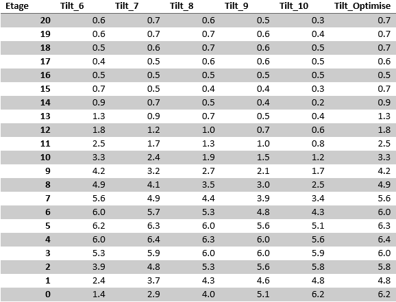
The results of the simulationTilt_Optimise correspond to the max level of all the other unique tilts.
Generalisation
This variant simulation can be done with a group of MSI files (antenna patterns), with for example multi-beam antenna.
|
When we set several MSI files, the gain and the electric tilt used in the simulation are the ones set in the antenna pattern. So, we can choose patterns with different gains. |
|---|
How is defined the power in this case?
If we set the input power, the EIRP of the simulation will be variable for each variant, and will be worth: EIRP = Input power + Gain (of the current pattern)

Multi-beam antenna