|
<< Click to display Table of content >> Interferences |
  
|
|
<< Click to display Table of content >> Interferences |
|
In case of a receiver in a free environment, the electric field is the addition of the incident waves and the reflected waves on the ground.
Interference between incident and reflected waves modify the overall electric field level. These interferences depend on the distance of the receiver from the antenna and on the wavelength.
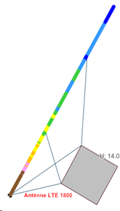
For this study we are working from an omnidirectional antenna, positioned 8 m high, with a power of 45 dBm. From this antenna we positioned receivers every 25 cm over a distance of 50 m in order to study the effects of interference.
Interference by frequency:
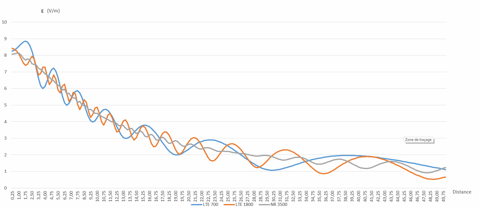
This graph shows the comparison of several frequencies (LTE700, LTE1800 and NR3500) on an asphalt ground.
Note that we simulate on a band, so several frequencies are used in a computation band and have effects on the final result since interferences depend upon frequency
Interference by ground material:
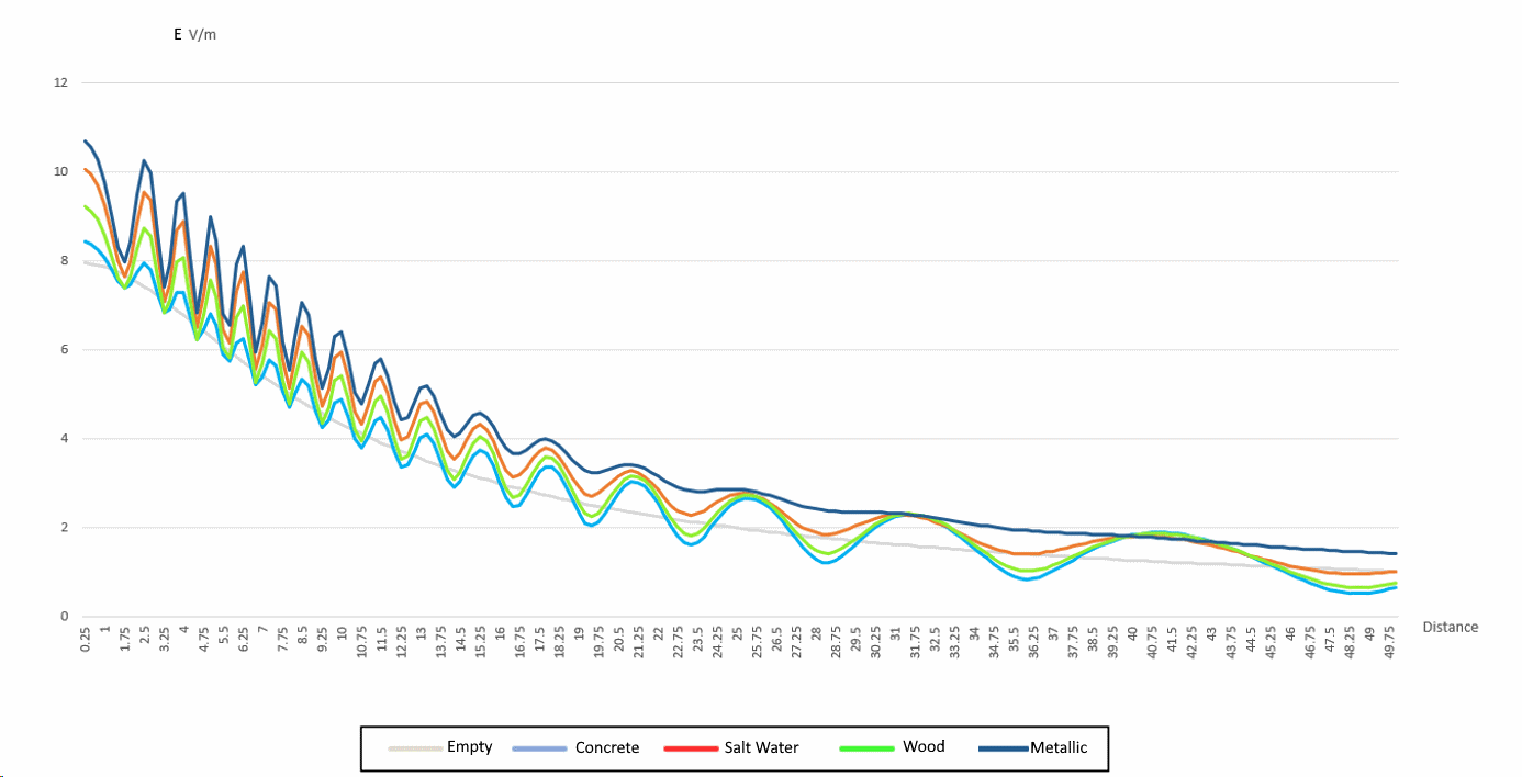
On these graphs, we can see the Electric field in V/m of each point according to 5 types of ground: empty, asphalt/concrete, salt water, wooded and metal on the LTE 1800 frequency band.
Interference as a function of antenna position
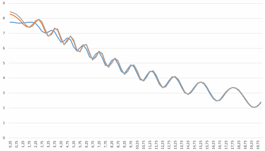
![]()
On these graphs, we can see the Electric field in V/m of each point according to the position of the antennas. The grey curve represents 1 antenna, the orange curve represents 3 antennas placed perpendicular to the straight line formed by all the calculation points, 8.5 dm from the antenna at (0; 0), and finally the blue curve also represents 3 antennas placed like the previous ones but 17 dm from the antenna at (0; 0). To be consistent, in cases where there are 3 antennas, the power of each antenna is divided by 3.
Interference depending on the presence and composition of a building
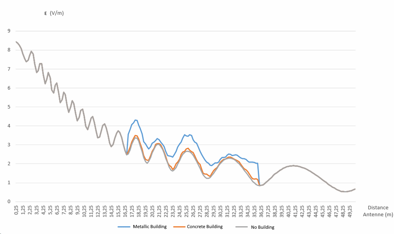
This graph compares field with and without building. The building have two materials, Concrete and Metallic.